Thursday, 26 November 2015
Part 2 START TO DRAW
The command "LINE".
Well at this point it's time to start drawing.
On the "draw" toolbar click the left mouse button on the command 'line'
is the key with this icon  = LINE
Now look what came written in the "command line".

The program suggesting steps that have to do to create a line, in this case is asking you to "Specify first point" (to specify the first point of the line).
Now click with the mouse in a point mean any of the canvas and then looks back at what appears in the "command line":
"Specify next point" (specify the second point).
Now move the mouse on one side and you'll see that you are creating a line, before clicking the second test with the mouse to rotate around the first point you've already laid down, you'll see the line that follows your movement in all directions .
Click and then at another point in the drawing slightly away from the first, doing so will create the first line between the two points just defined.
At this point, the program gives you the opportunity to continue to create more connected line segments to the first, by clicking with the mouse in other areas of the screen.
To stop the command and end the line, click the right mouse button, or press the "enter" key on your keyboard.
You can resume the command line just completed by pressing one of two buttons (right-click or enter), or by clicking again the "line" button  on the toolbar.
To create a line and then it took at least four clicks of the mouse:
beginning of the command, the first point, second point, the end of the control (Right).
To run the various commands of AutoCAD you must use different combinations of mouse buttons that we will see from time to time, with practice you will become automatic and runs them without thinking.
However, if during the execution of this or any other commands you seem to have some wrong step by clicking the "esc" key on your keyboard to quit the command and you can start over.
The latest versions of AutoCAD may be that during the execution of commands, some information and numbers will be displayed next to the cross-hairs, and repeat the "command line" informations, and others. It's called "dynamic input and can be turned off by clicking on the" DYN "bottom of the screen, under the command line.Personally I find it annoying but it is subjective, however, should turn it off initially.
The “ORTHO” function.
Now try to press the key "F8" on your keyboard and get the command line (line), click to establish the first point and then try to move the mouse back to it, you'll see that now the line no longer moves in all directions but only in the vertical and horizontal.
Click again to the second point of the line and then with the right to end the command.
Continue to press several times F8 and watch the "command line" and other small buttons below it.
Press "F8" then turn on or off the "ortho", or alternatively you can click on the button under the "command line".
This function key allows us to define with precision vertical and horizontal lines, but is also useful to move or copy items in a right angle with each other in technical design and therefore should be used whenever it can be activated or deactivated at any time, even during the execution of a command.
Drawing with AutoCAD you should not go to the event, although it seems to do so, should not be drawn without vertical or horizontal "ortho" activated.
Units of Autocad.
Resume 'line' command and with "ortho" mode activated, decide the first point of the line on the screen, then move the mouse on the right to create an horizontal line.
Now instead of clicking the second point of the line, dial a number with the keyboard, such as 100 and then press Enter or Right click twiceto confirm and exit the command.
As you understand you have just made a long line "100", but what is this value...?
For Autocad are 100 units, but you decide how to draw where they could be 100 millimeters, centimeters or meters.
It also depends on what you're drawing so there may be 100 mm of a metal object to draw on a locksmith, for example, was 100 cm if the side of a wooden table, or 100 meters of land for the fence.
Generally I'm happy with the cms, but it is good to learn how to handle various situations.
The thing to keep in mind however is that in Autocad we must generally think to draw in full scale 1:1 !I mean if I have a room of 4x4 meters and i draw considerations in cm, draw the long walls of the 400 units, which will consider just "cm", or 4000 units, which will consider "mm".
In general, you must draw by entering the actual measurements of what you represent, except in the case of magnified details you'll have to do on the same table.
It will be at the time of print design that will set a scale, (to the plot) as needed, and here things will change in the units with which we have interpreted the drawing (cm or mm.).
Let's say, for the print settings, it might be more correct to draw considering the "mm", but we'll talk about this in due course.
Setting units in the "Format" menu.
Let's then see another important approach to manage units.
From the menu "format" , click on "Units .."
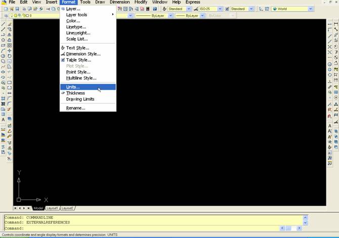
In the window that appears, click on the popup menu items "length" and "angle", respectively, sets "Decimal" and "Decimal Degrees" , as in the picture.
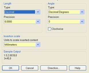
As you'll notice AutoCAD can be set for different types of units, such as "inch", which correspond to the "Architectural".
In our case the decimal units should be used for both the lengths to which the corners.
Attention: the unit settings menu does not apply in a general format for the program, but in this case affect one individual "files" that we'll made.
Click "OK" to confirm and close the window.
We will back on this when we print our design.
The "coordinates" of Autocad
Let us now see the "coordinates" of Autocad, even though they aren't crucial in simple designs, but it is still useful for understanding the operation of the program.
If you look at the bottom left, under the command line, as you move the mouse on the drawing you'll see the numbers move fast.
These numbers represent the XY coordinates of where the cursor is located.
By clicking on the mouse, enable or disable the coordinates.
A line drawn on the canvas will therefore have the X and Y coordinates for each of the two points that define the beginning and the end.
Basically we are drawing on a Cartesian plane.
UCS
We have seen that the UCS symbol represents the XY axis of that "Cartesian plane" on which we are designing and using the "ortho" we can constrain the Autocad drawing parallel to these axes.
If we wanted to draw for example 45 ° we can rotate the axis of the UCS.
To do this just type in the letters on the keyboard UCS and then press the enter key.
After typing the letter Z and then press Enter yet.
The letter Z indicates the third axis, it would be projected toward our eyes and it is the pivot around which rotate the axes X and Y.
Type 45 hours and then press Enter yet.
As you can see the UCS is rotated and with it the slider design, the command is completed. Drawing now "ortho" active we will be constrained to 45 °.
I now repeat the command, writes UCS and press Enter twice in a row, the UCS will be reported to the inclination of origin. Simple no?
We repeat again, type in UCS and then hit enter, now enter a E instead of Z, then hit enter.
The cursor changes to a selection handle, if we have a slanted line on the design and selection, clicking on the mouse, the UCS will catch on that line.
To bring it back to the origin, as before repeating the command and press Enter twice, or type a W instead of Z and then enter.
“OFFSET” command.
Until now we have a line drawn vertically or horizontally, the length of 100 units; imagine that they are centimeters.
Let us now see a new command "Offset , we find that this function on "modify" toolbar" and has this icon 
It allows us to make copies parallel to a line, or concentric in the case of a circle or a geometric figure, one side or the other to the line of origin.
Click on the "offset" and look at the "command line", the program asks:
"Specify offset distance" , type 50 on the keypad and press "enter".
At this point the program asks us where we want to do the offset line, appears on the command line says "select object to offset" and you'll notice how the cursor turns into a small square.
You can then click on the line after you created earlier and click again on either side of this anywhere in the drawing, it will create a copy of the first line at a distance of 100 units as we have stated above.
You can now click the right mouse button (or hit Enter on the keyboard) to exit the command offset, or continue by selecting one of the lines and still make others equidistant offset.
Please note that running two or more offset of the same line in the same side, we'll create overlapping lines, we will see one but are actually more, is a classic mistake by trying to avoid.
Then:
A click on the command  , Enter the offset distance and press enter to confirm it. Click the object to copy and then click again on either side of this, to create the copy, repeat these last two steps to make other offsets or click the right button to enter and exit from the command.
PART -1 AUTOCAD INTERFACE AND PRELIMINARY SETTINGS
I will give to assume that the program is already installed on your computer and ready for use.
If you do not have the program you can download a trial version from Autodesk's website at:
http://usa.autodesk.com/adsk/servlet/pc/index?siteID=123112&id=13706332
When you start Autocad will be presented with a window similar to the one below.
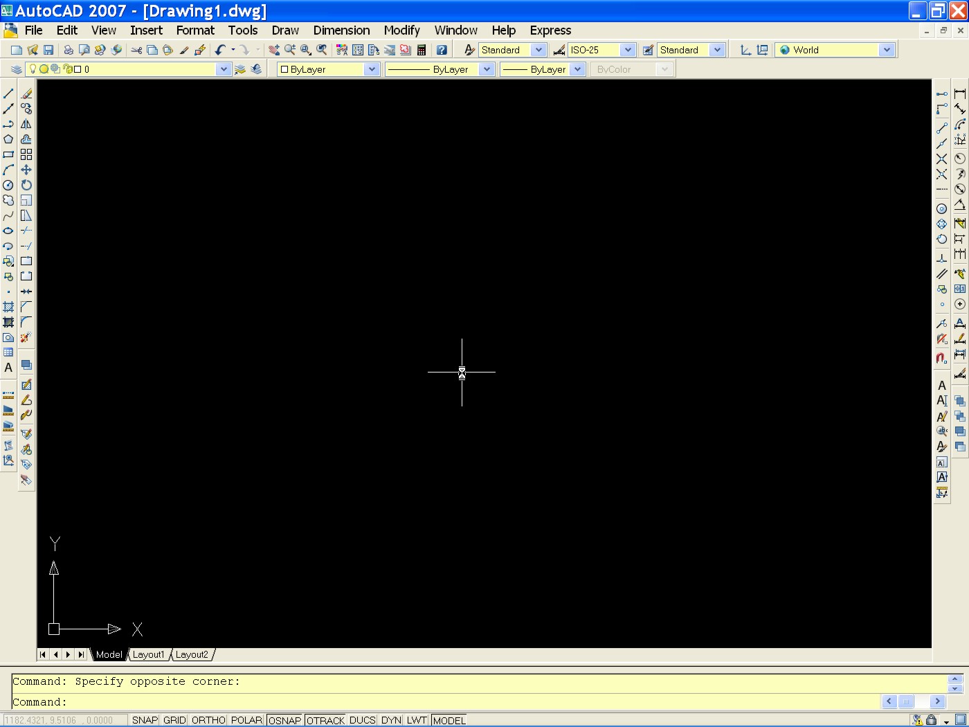
And here is our program, you see similar to almost all Windows programs comes with a row of pop-up menu at the top with the commands "file, edit, view, insert" and so on.. , and several "toolbars" . All those buttons, which correspond to various commands that we will see below, are divided into groups, the "toolbars", which can be customized to make them visible or invisible, and move into desired position.
In the picture above this interface has already been partially done, so you might see things arranged differently from how have you on your screen.
Do not worry about it for now, also depending on the version of Autocad, icons may look slightly different, but basically the symbols represented at least for the main controls are the same.
Then we have the central area, that the drawing area (usually a black background), with the center of the cursor or " crosshairs " controlled by the mouse.
In addition to this in the bottom left, still in the drawing area, you should see an icon with two arrows and the letters X, Y
This is the icon called "UCS" and represents the coordinate axes X, Y on which you move the crosshairs.
A large part of very important and I ask you to remember is the "command line" , which is the window at the bottom on two or more lines at the bottom where you see write "command:".
It 's very important especially in the beginning you get used to observe what is written in this window when you run the command,Autocad every time you use a command here shows you the steps to run it.

Introduction to "Toolbars"
Well, back to the "toolbar" and see the first two to be taken into consideration.
The "draw" toolbar

And the "modify" toolbar

Ideally they should already be visible to the sides of the canvas, perhaps a right, left and arranged vertically.
If not, move the pointer over any button of the toolbar and click on this with the RIGHT CLICK of mouse, will bring up a menu like the one shown in the picture.
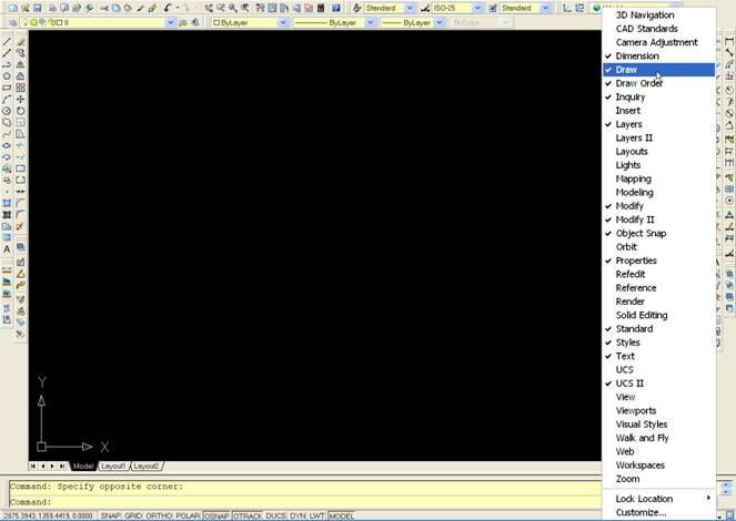
The entries in this menu correspond to the various "toolbar" visible and invisible, and as you have probably realized by this entry can be enabled or disabled.
Click on the items "draw" and "modify" to make this toolbar visible.
When they appear in the drawing area you can move by clicking and holding the button on its top in blue and drag them (one at a time) on the left side of the screen, at some point you'll see that you will have automatically vertically, then Release the mouse button .
In this way, you can customize the interface of the program as desired by activating the toolbar that you use frequently and placing them where you want it, on right, at the top left or above the drawing area etc.
Preliminary Settings
Before you start drawing we see a couple of other things.
Click your mouse on the menu "Tools"> "Options .." as in the image below.
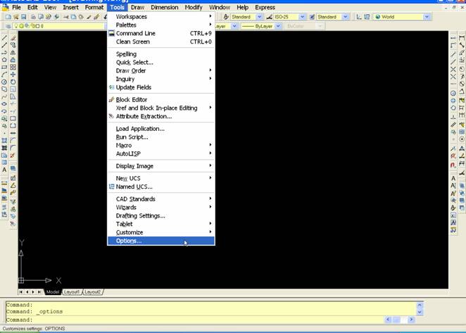
You'll see a window containing a number of tables from which you can set a whole series of things such as background color, the command line, and other parameters that affect the operation of the program.
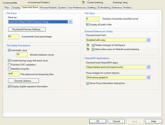
Ok, now click the "Open and Save" and under the "save as" open the popup menu by clicking the arrow to the side.
It's the one highlighted in blue in the previous image...
In this menu you'll see some entries with the words:
AutoCAD2007 drawing (*. dwg)
AutoCAD2004 drawing (*. dwg)
AutoCAD 2000 Drawing (*. dwg)
etc..
These entries written on the side (*. dwg) represent the types of files that our program can open and save. More specifically, for example by setting this item to "AutoCAD 2000" set Autocad that every time you save a drawing that we did or we open, it is saved in AutoCAD 2000 format.
What does this mean?
As you might know there are different versions of AutoCAD and comes out every 1-2 years a new, the latest "release" is the 2015.
(Of this, like the previous ones, there is a version LT (light) and the normal, full.The light version does not have the ability to create designs in 3D (three dimensional), but can open and view them, while with the most comprehensive and expensive full version can be created through tools and additional commands).
The most important difference between the "release" of program is that older versions can not open drawings created by the later versions, unless those who have saved the file has not set his program for saving in a old version, as explained before.
This is very important to know especially when collaborating with other users and you have to give or receive drawings.
Beyond this, every file saved from AutoCAD will be of type "dwg", the files as normally autocad manage have "dwg" extension.
For example, if we save a drawing and call it "Plan" or "kitchen" will be automatically saved in this way:
plan.dwg
kitchen.dwg
Where the point. separates the filename from its extension, which identifies a file type to another.
There are indeed many types of files with many different extensions:
"Pianta.doc" would be a text document
"Pianta.bmp".Gif, .Jpg, .Tiff and others, would rather the images.
I digress a bit 'from Autocad but if you're not already aware, this information will be useful.
The "dwg" however, is not the only type of file that can be read and saved from AutoCAD, but we will see this later.
Then return to the Options window of Autocad, and always in the "open and save.
look further down the "Automatic Save" (Auto-Save), which should already be enabled, and the window of the "Minutes Between saves" (Minutes of each save) type such as 10.
In this way, Autocad perform an automatic save every 10 minutes the drawing you're working on, and put it in a specific folder.
This feature is very useful for not losing your work as you'll see that sometimes the program crashes, or leaves the current or accidentally delete the file you were working.
You will then be possible (and useful) to go back to the file that was saved in AutoCAD automatically, as we shall see ....
We are now going to set the right click of the mouse.
Also in the options window, click on the table "user preferences (user preferences) and then again click on the button at the top left" right-click customization (customization right mouse button).
In the window that appears, activate the first box for each item, click on it for the following items.
-Default mode, edit mode, command mode-
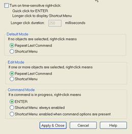
According to the release of AutoCAD you have, you can alternatively check the first entry is in the window, turn on time-sensitive right click.
Finally, click on "Apply & Close".
In this way, clicking the right mouse button, after completing a command, AutoCAD will repeat it.
If you just finished drawing a line for example, after clicking the right button will be repeated the command "line", and so for all other commands.
This feature helps a lot to speed up the work, accustomed to use it, during the course you'll often put into practice.
On the Table "display" click on the "colors" , will open the window you see below on which to set the colors of the program interface.
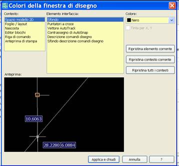
On this window select the central area at the top, the first item in the "background" and then open the color menu on the right and select the desired color for the background. Usually used black.
After click "apply and close" to assign changes made to the colors.
Now click "OK" at the bottom of options window, to close it and accept the changes.
What has been said so far are general settings to be done only once, the next time you open AutoCAD will not need to repeat them.
If Autocad crashes before you have it closed and reopened, the settings will be lost as they are made.
SUMMARY:
Open Autocad, customize the interface and activating the toolbar and fixed to the screen. (We have seen thus far, "draw" and "modify").
Open the Options dialog from the "tools> options .." and set the auto-save, if necessary set the save to older versions. (For the moment leave it as it is with the default setting).
Also in the options dialog set preferences for the right mouse button, the table "user preferences."
From the chart "display options" if you prefer set the background color to black.
Friday, 20 November 2015
CONCRETE FRAME STRUCTURES
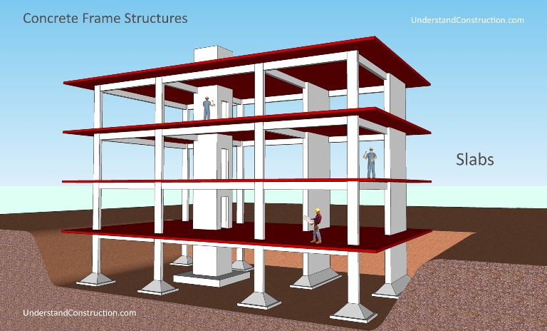
Concrete frame structures are a very common - or perhaps the most common- type of modern building. As the name suggests, this type of building consists of a frame or skeleton of concrete. Horizontal members of this frame are called beams, and vertical members are called columns. Humans walk on flat planes of concrete called slabs. Of these, the column is the most important, as it is the primary load-carrying element of the building (See figure 2 at the bottom of the page for an illustration of each of the major parts of a frame structure). If you damage a beam in a building, it will usually affect only one floor, but damage to a column could bring down the entire building.
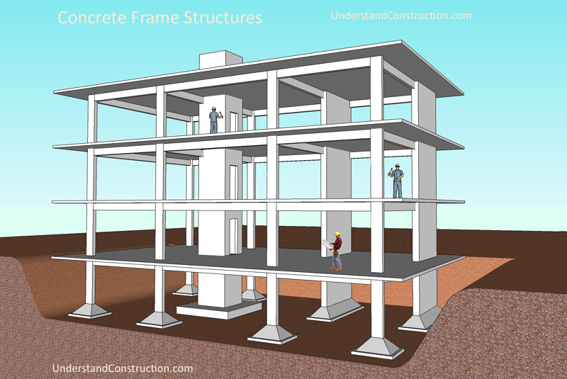
When we say concrete in the building trade, we actually mean reinforced concrete. Its full name is reinforced cement concrete, or RCC. RCC is concrete that contains steel bars, called reinforcement bars, or rebars. This combination works very well, as concrete is very strong in compression, easy to produce at site, and inexpensive, and steel is very very strong in tension. To make reinforced concrete, one first makes a mould, called formwork, that will contain the liquid concrete and give it the form and shape we need. Then one looks at the structural engineer's drawings and places in the steel reinforcement bars, and ties them in place using wire. The tied steel is called a reinforcement cage, because it is shaped like one. Once the steel is in place, one can start to prepare the concrete, by mixing cement, sand, stone chips in a range of sizes, and water in a cement mixer, and pouring in the liquid concrete into the formwork tilll exactly the right level is reached. The concrete will become hard in a matter of hours, but takes a month to reach its full strength. Therefore it is usually propped up until that period. During this time the concrete must be cured, or supplied with water on its surface, which it needs for the chemical reactions within to proceed properly.
So the structure is actually a connected frame of members, each of which are firmly connected to each other. In engineering parlance, these connections are calledmoment connections, which means that the two members are firmly connected to each other. There are other types of connections, including hinged connections, which are used in steel structures, but concrete frame structures have moment connections in 99.9% of cases. This frame becomes very strong, and must resist the various loads that act on a building during its life.
These loads include:
- Dead Loads: the downwards force on the building coming from the weight of the building itself, including the structural elements, walls, facades, and the like.
- Live Loads: the downwards force on the building coming from the expected weight of the occupants and their possessions, including furniture, books, and so on. Normally these loads are specified in building codes and structural engineers must design buildings to carry these or greater loads. These loads will vary with the use of the space, for example, whether it is residential, office, industrial to name a few. It is common for codes to require live loads for residential to be a minimum of about 200 kg/m2, offices to be 250 kg/m2, and industrial to be 1000 kg/m2, which is the same as 1T/m2. These live loads are sometimes called imposed loads.
- Dynamic Loads: these occur commonly in bridges and similar infrastructure, and are the loads created by traffic, including braking and accelerating loads.
- Wind Loads: This is a very important design factor, especially for tall buildings, or buildings with large surface area. Buildings are designed not to resist the everyday wind conditions, but extreme conditions that may occur once every 100 years or so. These are called design windspeeds, and are specified in building codes. A building can commonly be required to resist a wind force of 150 kg/m2, which can be a very significant force when multiplied by the surface area of the building.
- Earthquake Loads: in an earthquake, the ground vigorously shakes the building both horizontally and vertically, rather like a bucking horse shakes a rider in the sport of rodeo. This can cause the building to fall apart. The heavier the building, the greater the force on it. Its important to note that both wind and earthquake imposehorizontal forces on the building, unlike the gravity forces it normally resists, which are vertical in direction.
The concrete frame rests on foundations, which transfer the forces - from the building and on the building - to the ground.
 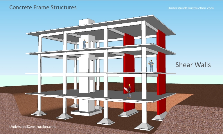 |
Shear Walls are important structural elements in high-rise buildings. Shear walls are essentially very large columns - they could easily measure 400mm thick by 3m long - making them appear like walls rather than columns. Their function in a building is to help take care of horizontal forces on buildings like wind and earthquake loads. Normally, buildings are subject to vertical loads - gravity. Shear walls also carry vertical loads. It is important to understand that they only work for horizontal loads in one direction - the axis of the long dimension of the wall. These are usually not required in low-rise structures.
Elevator Shafts are vertical boxes in which the elevators move up and down - normally each elevator is enclosed in its own concrete box. These shafts are also very good structural elements, helping to resist horizontal loads, and also carrying vertical loads.
walls in concrete frame buildings
When brick or concrete blocks are used, it is common to plaster the entire surface - brick and concrete - with a cement plaster to form a hard, long-lasting finish.
cladding of concrete frame structures
Thursday, 19 November 2015
Topics under Quantity Surveying
Types of Footings
Types of columns
WHAT IS CIVIL ENGINEERING
 |
| WHAT IS CIVIL ENGINEER |

