Part 2 START TO DRAW
The command "LINE".
Well at this point it's time to start drawing.
On the "draw" toolbar click the left mouse button on the command 'line'
is the key with this icon  = LINE
Now look what came written in the "command line".

The program suggesting steps that have to do to create a line, in this case is asking you to "Specify first point" (to specify the first point of the line).
Now click with the mouse in a point mean any of the canvas and then looks back at what appears in the "command line":
"Specify next point" (specify the second point).
Now move the mouse on one side and you'll see that you are creating a line, before clicking the second test with the mouse to rotate around the first point you've already laid down, you'll see the line that follows your movement in all directions .
Click and then at another point in the drawing slightly away from the first, doing so will create the first line between the two points just defined.
At this point, the program gives you the opportunity to continue to create more connected line segments to the first, by clicking with the mouse in other areas of the screen.
To stop the command and end the line, click the right mouse button, or press the "enter" key on your keyboard.
You can resume the command line just completed by pressing one of two buttons (right-click or enter), or by clicking again the "line" button  on the toolbar.
To create a line and then it took at least four clicks of the mouse:
beginning of the command, the first point, second point, the end of the control (Right).
To run the various commands of AutoCAD you must use different combinations of mouse buttons that we will see from time to time, with practice you will become automatic and runs them without thinking.
However, if during the execution of this or any other commands you seem to have some wrong step by clicking the "esc" key on your keyboard to quit the command and you can start over.
The latest versions of AutoCAD may be that during the execution of commands, some information and numbers will be displayed next to the cross-hairs, and repeat the "command line" informations, and others. It's called "dynamic input and can be turned off by clicking on the" DYN "bottom of the screen, under the command line.Personally I find it annoying but it is subjective, however, should turn it off initially.
The “ORTHO” function.
Now try to press the key "F8" on your keyboard and get the command line (line), click to establish the first point and then try to move the mouse back to it, you'll see that now the line no longer moves in all directions but only in the vertical and horizontal.
Click again to the second point of the line and then with the right to end the command.
Continue to press several times F8 and watch the "command line" and other small buttons below it.
Press "F8" then turn on or off the "ortho", or alternatively you can click on the button under the "command line".
This function key allows us to define with precision vertical and horizontal lines, but is also useful to move or copy items in a right angle with each other in technical design and therefore should be used whenever it can be activated or deactivated at any time, even during the execution of a command.
Drawing with AutoCAD you should not go to the event, although it seems to do so, should not be drawn without vertical or horizontal "ortho" activated.
Units of Autocad.
Resume 'line' command and with "ortho" mode activated, decide the first point of the line on the screen, then move the mouse on the right to create an horizontal line.
Now instead of clicking the second point of the line, dial a number with the keyboard, such as 100 and then press Enter or Right click twiceto confirm and exit the command.
As you understand you have just made a long line "100", but what is this value...?
For Autocad are 100 units, but you decide how to draw where they could be 100 millimeters, centimeters or meters.
It also depends on what you're drawing so there may be 100 mm of a metal object to draw on a locksmith, for example, was 100 cm if the side of a wooden table, or 100 meters of land for the fence.
Generally I'm happy with the cms, but it is good to learn how to handle various situations.
The thing to keep in mind however is that in Autocad we must generally think to draw in full scale 1:1 !I mean if I have a room of 4x4 meters and i draw considerations in cm, draw the long walls of the 400 units, which will consider just "cm", or 4000 units, which will consider "mm".
In general, you must draw by entering the actual measurements of what you represent, except in the case of magnified details you'll have to do on the same table.
It will be at the time of print design that will set a scale, (to the plot) as needed, and here things will change in the units with which we have interpreted the drawing (cm or mm.).
Let's say, for the print settings, it might be more correct to draw considering the "mm", but we'll talk about this in due course.
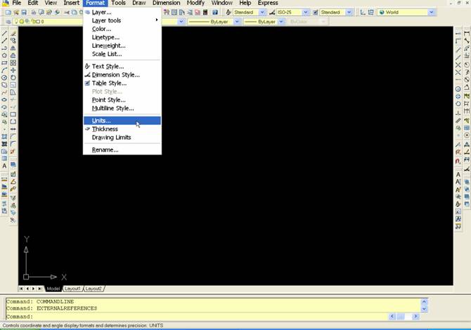
Setting units in the "Format" menu.
Let's then see another important approach to manage units.
From the menu "format" , click on "Units .."

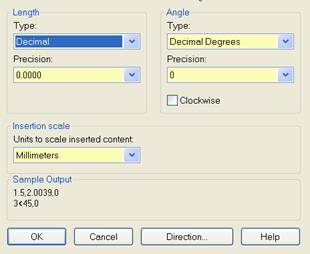
In the window that appears, click on the popup menu items "length" and "angle", respectively, sets "Decimal" and "Decimal Degrees" , as in the picture.

As you'll notice AutoCAD can be set for different types of units, such as "inch", which correspond to the "Architectural".
In our case the decimal units should be used for both the lengths to which the corners.
Attention: the unit settings menu does not apply in a general format for the program, but in this case affect one individual "files" that we'll made.
Click "OK" to confirm and close the window.
We will back on this when we print our design.
The "coordinates" of Autocad
Let us now see the "coordinates" of Autocad, even though they aren't crucial in simple designs, but it is still useful for understanding the operation of the program.
If you look at the bottom left, under the command line, as you move the mouse on the drawing you'll see the numbers move fast.
These numbers represent the XY coordinates of where the cursor is located.
By clicking on the mouse, enable or disable the coordinates.
A line drawn on the canvas will therefore have the X and Y coordinates for each of the two points that define the beginning and the end.
Basically we are drawing on a Cartesian plane.
UCS
We have seen that the UCS symbol represents the XY axis of that "Cartesian plane" on which we are designing and using the "ortho" we can constrain the Autocad drawing parallel to these axes.
If we wanted to draw for example 45 ° we can rotate the axis of the UCS.
To do this just type in the letters on the keyboard UCS and then press the enter key.
After typing the letter Z and then press Enter yet.
The letter Z indicates the third axis, it would be projected toward our eyes and it is the pivot around which rotate the axes X and Y.
Type 45 hours and then press Enter yet.
As you can see the UCS is rotated and with it the slider design, the command is completed. Drawing now "ortho" active we will be constrained to 45 °.
I now repeat the command, writes UCS and press Enter twice in a row, the UCS will be reported to the inclination of origin. Simple no?
We repeat again, type in UCS and then hit enter, now enter a E instead of Z, then hit enter.
The cursor changes to a selection handle, if we have a slanted line on the design and selection, clicking on the mouse, the UCS will catch on that line.
To bring it back to the origin, as before repeating the command and press Enter twice, or type a W instead of Z and then enter.
“OFFSET” command.
Until now we have a line drawn vertically or horizontally, the length of 100 units; imagine that they are centimeters.
Let us now see a new command "Offset , we find that this function on "modify" toolbar" and has this icon 
It allows us to make copies parallel to a line, or concentric in the case of a circle or a geometric figure, one side or the other to the line of origin.
Click on the "offset" and look at the "command line", the program asks:
"Specify offset distance" , type 50 on the keypad and press "enter".
At this point the program asks us where we want to do the offset line, appears on the command line says "select object to offset" and you'll notice how the cursor turns into a small square.
You can then click on the line after you created earlier and click again on either side of this anywhere in the drawing, it will create a copy of the first line at a distance of 100 units as we have stated above.
You can now click the right mouse button (or hit Enter on the keyboard) to exit the command offset, or continue by selecting one of the lines and still make others equidistant offset.
Please note that running two or more offset of the same line in the same side, we'll create overlapping lines, we will see one but are actually more, is a classic mistake by trying to avoid.
Then:
A click on the command  , Enter the offset distance and press enter to confirm it. Click the object to copy and then click again on either side of this, to create the copy, repeat these last two steps to make other offsets or click the right button to enter and exit from the command.


No comments:
Post a Comment